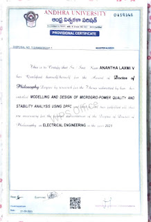
1.Received Ph.D on 10/8/2023.


3.Attended ATAL FDP

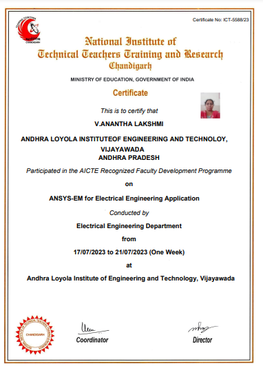
4. NITTR Certificate
1.Received Ph.D on 10/8/2023.
ANDHRA
LOYOLA INSTITUTE OF ENGINEERING AND TECHNOLOGY
DC
MACHINES AND TRANSFORMERS(R20)
QUESTION
BANK
IIND
YEAR I SEM
Unit-1
1.Find expression for magnetic force
developed in a doubly-excited translational magnetic system. (10M) [L1]
2.Explain the construction and principle
of operation of DC generator. (10M) [L1]
3. Find expression for magnetic force
developed in a singly-excited translational magnetic system. (10M)
4. Explain characteristics DC generators. (10M)
[L1]
5) Determine (i) the total torque
developed (ii) the useful torque of a 250 V, 4 pole series motor with 782 wave
connected conductors developing 8 kW and taking 40 A with a flux per pole of 25
mWb. The armature resistance of the motor is 0.75 ohms.(5M) [L2]
6.explain different types of excitation
techniques of DC Generators(10M) [L1]
7. A 20 kW, 250 V, 6 pole lap connected
dc generator runs at 1250 rpm. Armature has 550 conductors. For full load armature – ohmic loss
of 250 Wfind the useful flux per pole. Take 2 V as the brush drop at full
load.and give applications(5m) [L2]
8.Derive EMF equation of DC Generators(10M) [L1]
Unit-2
1.Explain the construction and principle
of operation of DC Motor. (10M) [L1]
2.Explain the mechanical and electrical
characteristics of dc cumulative and differential dc motors. (10M) [L1]
3. Determine (i) the total torque
developed (ii) the useful torque of a 250 V, 4 pole series motor with 782 wave
connected conductors developing 8 kW and taking 40 A with a flux per pole of 25
mWb. The armature resistance of the motor is 0.75 ohms. (5M) [L2]
4.explain the concept of armature
reaction of dc motor [L1] (10M)
5.explain the concept of losses and
efficiency and application of dc motor
(5M) [L1]
6.explain the concept of 3 point starter
with neat diagram (10M) [L1]
7. explain the concept of 4 point
starter (10M) [L1]
8. A 230 V DC Shunt motor takes 32 A at
full-load. Find the back emf on full load if the resistances of
motor armature and shunt field windings are 0.22 Ω and 120Ω respectively. (5M) [L2]
Unit-3
1.explain speed control technquies of DC
shunt motor (10M) [L1]
2. Explain the procedure of conducting
brake-test on DC machine with a neat circuit diagram(10M) [L1]
3. . Explain the procedure of conducting swinbunes -test on DC machine with a neat circuit diagram(10M) [L1]
4. . Explain the procedure of
conducting hopkinsonson -test DC machine
with a neat circuit diagram
And Explain concept of
separation of losses(10M) [L1]
5. In a retardation test on a D.C motor, with its field normally
excited, the speed
fell
from 1525 to 1475 in 25 seconds. With an average load of 1 kW supplied by the armature, the
same speed drop occurred in 20 seconds. Find the moment of inertia of the
rotating parts in kg.m2(5M) [L2]
MID – II Q.B
Unit - 3
7.. Discuss the working principle of
single-phasetransformer and also explain the constructional details(10M) [L1]
8..Derive the emf equation of a
transformer. (5M) [L1]
9.explain the concept of
transformer on no load condition with phasor diagram[L1] (10M)
10.explain the concept of
transformer on load condition with
phasor diagram[L1] (10M)
11. .explain the concept of
transformer on unity power factor with phasor diagram [L1] (10M)
12.draw and explain equivalent
circuit of transformers [L1] (10M)
13. In a 50-kVA, 11-kV/400-V, single-phase
transformer, the iron and copper losses are 500 W and 600 W,
respectively under rated conditions. Calculate (a) the efficiency at unity
power factor at full-load, (b) the load for maximum efficiency, and (c)
the iron and copper losses for this load. [L2] (5M)
Unit-4
1.A 4.5 kVA, 400/210 V,50 Hz single phase
transformer has the following test
data:
O.C. test (l.v.side) 210V, 1A,70 W
S.C. test (h.v.side) 15 V, 10.8A, 100 W
Calculate (i) Equivalent circuit
referred to l.v side and
(ii) Secondary load voltage on full load
at 0.8 power factor lagging
(iii) Efficiency of transformer at ¾ th
load and 0.7 power factor (lag).
[L2] (10M)
2. In a 400 V, 50 Hz transformer, the total
iron loss is 2300 W. When the supply
voltage and the frequency reduced to 200 V and 25 Hz respectively the
corresponding loss is 800 W. Calculate
the eddy current loss at normal voltage and frequency. [L2] (5M)
3. A 2-winding 10 kVA, 440/110 V transformer
is reconnected as a step-down 550/440 V autotransformer. Compare volt-ampere
rating of the autotransformer with that of original 2-winding transformer.
Calculate power transferred to the load: (i) inductively (ii) conductively [L2]
(5M)
4. The voltage per turn of a
single-phase transformer is 1.1V. When the primary winding is connected to a 220V, 50Hz A.C supply, the secondary
voltage is
found to
be 550V. Find: i) Primary and secondary
turns ii) Core area if the maximum flux density is 1.1 Wb/m2 [L2] (5M)
5. A 220 V , 2.8 KVA
single phase transformer has an iron loss of 120 W at 45 Hz and 70 W at 35 Hz. Find the hysteresis
and eddy current losses at 50 Hz [L2]
(5M)
6. A single phase, 25 KVA, 2000/200V
transformer has iron loss is 350W and full load copper loss is
400W. Calculate the efficiency at unity power factor on full load and half load?
[L2] (5M)
7. What is sumpner’s test and explain
its principle with a neat circuit diagram
[L1] (5M)
8. What is O.C and S.C test and explain its principle with a neat
circuit diagram L1] (5M)
9.explain the operation of parallel
operation of transformers [L1] (5M)
10. Two transformers A and B are
connected in parallel to supply a load having an impedance of (2 + j 1.5)O. The equivalent
impedances referred to the secondary windings are (0.15 + j 0.5)O and (0.1 + j 0.6)O respectively. The
open-circuite.m.f. of A is 207 V and of B is 205 V. Calculate
(i) the voltage at the load
(ii) the power supplied to the load
(iii) the power output of each transformer
and
(iv) the kVA input to each transformer.
[L2] (10M)
Unit-5
1. What is the total load capacity of V-V
bank as compared with a delta-delta bank?
(5M)
[L1]
2. Explain the concept of Scott connection
(three phase to two phase) conversion with a neat circuit diagram. (5M)
[L1]
3. Derive an expression for saving of
copper in it when compared to ordinary two winding transformer? (5M) [L1]
4. Explain open delta (or V – V )
connection with neat diagrams (5M) [ L1]
5. In a Sumpner’s test on two identical
single – phase transformers rated 750 kVA, 11/0.5 kV, 50 Hz the wattmeter
reading on h.v side is 8000 W and on the l.v side is 16000W. Find the
efficiency of each transformer on half full load and 0.78 power factor. What
will be its maximum efficiency (5M)
[
L2]
6. A balanced 3-phase, 100 kW load at
400V and 0.8 p.f. lag is to be obtained from a balanced 2-phase, 1100V lines.
Determine the kVA rating of each unit of the Scott-connected transformer. [ L2]
7. A balanced 3-phase, 100 kW load at
400V and 0.8 p.f. lag is to be obtained from a balanced 2-phase, 1100V lines.
Determine the kVA rating of each unit of the Scott-connected transformer. (5M)
[
L2]
8. What are the advantages of poly-phase
transformers? Give different configurations (5M)
[
L2]
UNIT-2
Time Response Analysis Standard test signals – time response of first and second order systems – time domain specifications, steady state errors and error constants, P, PI,
Stability and Root Locus Technique
The concept of stability – Routh’s stability criterion –limitations of Routh’s stability, Root locus concept – construction of root loci (simple problems).Effect of addition of poles and zeros root locus
UNIT-1
Mathematical Modeling of Control Systems Classification of control systems, open loop and closed loop control systems and their differences, Feedback characteristics, transfer function of linear system, differential equations of electrical networks, translational and rotational mechanical systems, transfer function of DC servo motor – AC servo motor – synchro, transmitter and receiver – block diagram algebra – representation by signal flow graph – reduction using Mason’s gain formula.
Teacher/Instructor: Mrs.V.Anantha Lakshmi Department
of Electrical & Electronics Engineering Assistant Professor of EEE
Lesson Plan for a Day
IV B.Tech, Sem – I 2019-20
|
Programme |
B.Tech, Electrical&ElectronicsEngineering |
|
Semester |
IV
Year-ISemester |
|
SubjectTitle |
PSOC |
|
SubjectCode |
R1641023 |
|
ClassHours |
5-Hoursperweek |
|
TotalHours |
70 |
|
Credits |
3 |
|
MaxMarks |
100 |
|
Unit&Title |
Unit-I:
- Economic Operation of Power Systems |
|
TeachingandLearning |
BlackBoard/PowerPointPresentation/Videos,E-material. |
|
Detailed – Lesson 1 Optimal operation of Generators in Thermal power
stations LessonObjectives: |
|
|
Factual |
Able
to compute optimal scheduling of Generators. Able
to understand hydrothermal scheduling. |
|
Conceptual |
Understand the
unit commitment problem. Understand
importance of PID controllers in single area and two area systems |
|
Procedural |
Able to understand importance of the frequency. |
|
Applied |
Will
understand reactive power control and line power compensation. |
Pre requisite Knowledge:
Working of
thermal power generating stations
Discussion
·
Students will be able to remember the influencing
parameters.
·
The pre-task activity material will give them a conceptual
knowledge of how to get the optimum generation cost and its function
Summary
· To get optimum generation cost the incremental fuel costs of the individual thermal generating units must be same.
· At this condition we will come to know what is the load sharing of individual generating units.
References
Text Books:
·
T1.
Electric Energy systems Theory – by O.I.Elgerd, Tata McGraw–hill Publishing
Company
Ltd., Second edition.
·
T2.
Power System stability & control, Prabha Kundur,TMH
·
T3.
Modern Power System Analysis – by I.J.Nagrath & D.P.Kothari sTata Mc Graw –
Hill
Publishing Company
Ltd, 2nd edition.
Reference Books:
·
R1.Power
System Analysis and Design by J.Duncan Glover and M.S.Sarma, THOMPSON,
3rd Edition.
·
R2.
Power System Analysis by Grainger and Stevenson, Tata McGraw Hill.
·
R3.
Power System Analysis by Hadi Saadat – TMH Edition.
|
Taxonomy of Objectives: Specific Outcomes |
||||||
|
KnowledgeDimension |
The Cognitive Process Dimension |
|||||
|
Remember |
Understand |
Apply |
Analyze |
Evaluate |
Create |
|
|
A.FactualKnowledge |
SO-1,2 |
SO-1,2,3 |
SO-1,2,3 |
|
|
|
|
B. ConceptualKnowledge |
SO-1,2,3 |
SO-1,2,3 |
SO-1,2,3 |
|
|
|
|
C. ProceduralKnowledge |
|
|
|
|
|
|
1.Received Ph.D on 10/8/2023. 2. Certified UHV Course 3.Attended ATAL FDP 4. NITTR Certificate